


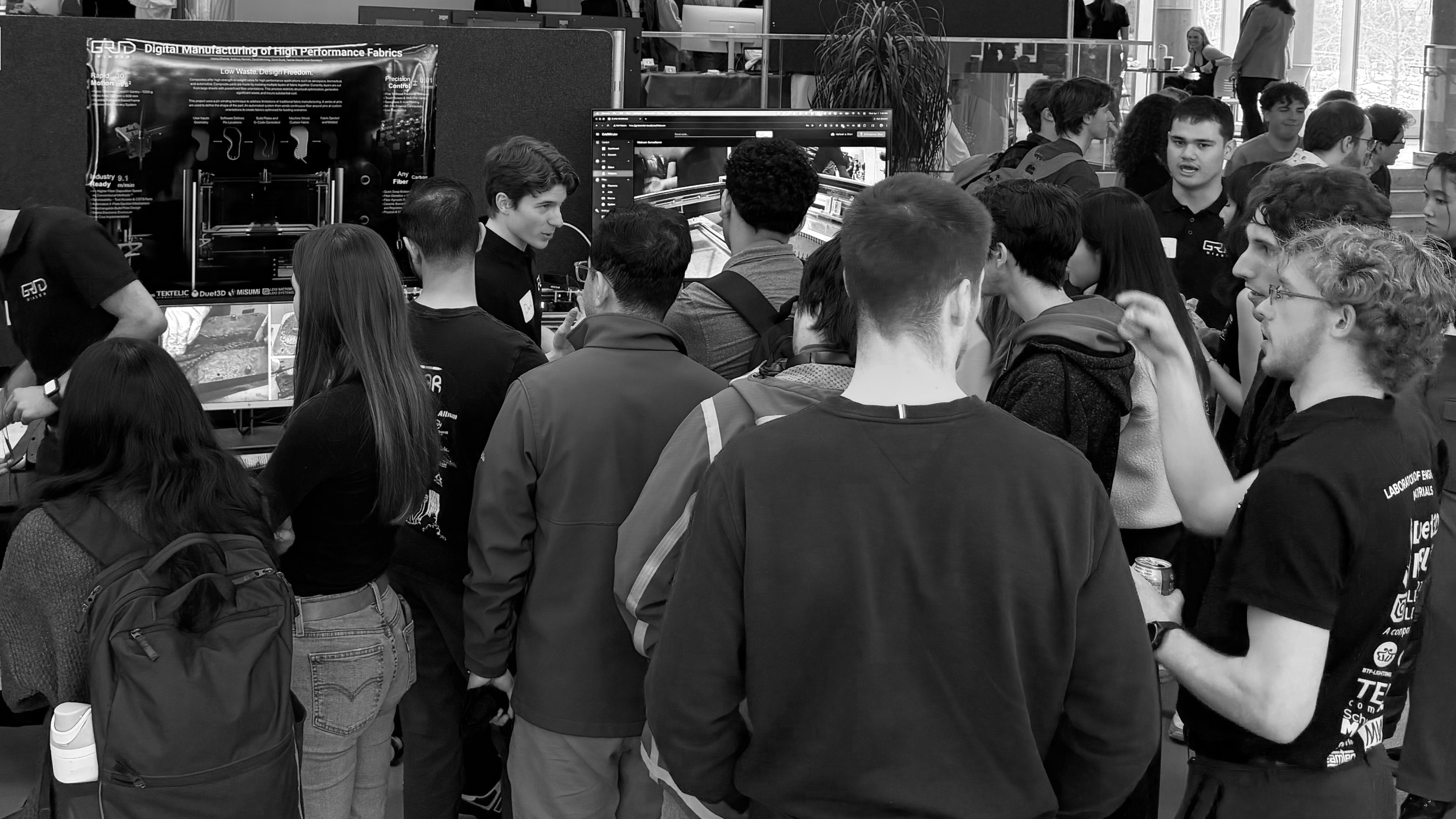
GridWinder
GridWinder transforms continuous fiber into custom reinforcement geometries with near-zero waste—automating the path from spool to mold.
OVERVIEW + BACKGROUND
Concept to Reality
Laboratory of Engineering Materials
Role: Hardware & mechanism Design
Project Duration: Eight Months
Team Members: Six


Global demand for carbon fiber increased 43.8% in 2024 alone.

30% of all CNC-cut carbon fiber is wasted before reaching final form.

Global carbon fiber supply is 170,000 tonnes, a shortfall of 55,000 tonnes.

Producing carbon fiber requires 510 MJ/kg. Steel requires 22 MJ/kg.

Interviewing experts in the field of composites revealed that despite their exceptional properties, slow prototyping times, high fabrication costs, skilled labour requirements and limited options for recyclability prevent industry adoption.
By reducing the barriers to entry, materials previously only accessible to large corporations could benefit researchers, startups, and makers. As more innovators gain access to composites, the potential for a more sustainable future grows.
Overview
Zero Wasted Material
From hand-winding fiber around pins to automated precision placement, GridWinder was designed to reinvent composite fabrication.
A New Approach
Optimize Orientation
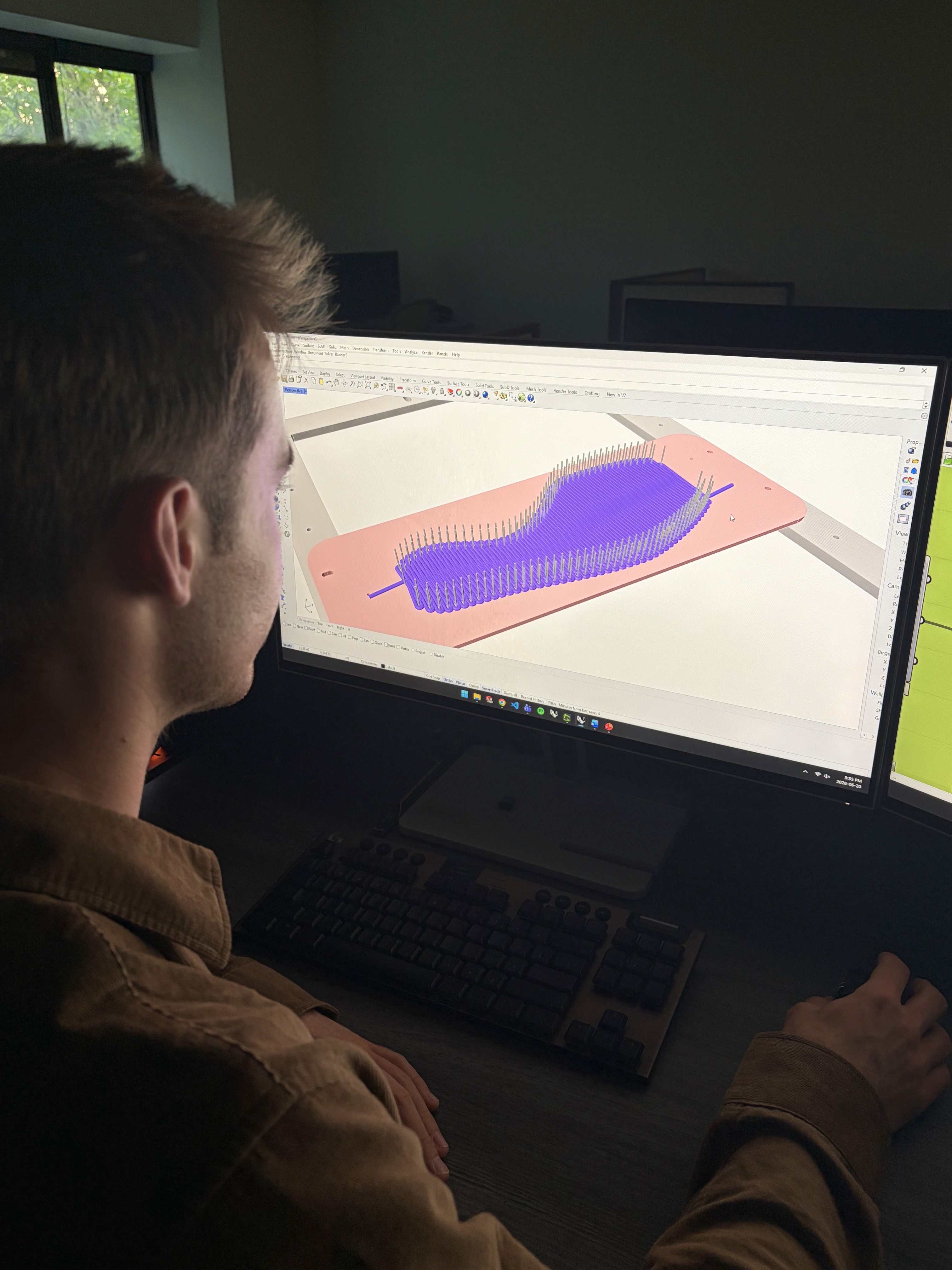
GridWinder provides an end-to-end workflow where engineers can import a part directly into the software, flatten its geometry, and automatically generate the pin layout required to manufacture it.
Because engineering fibers are anisotropic, fiber orientation can be adjusted in real time to reinforce specific loading directions and tailor the part's mechanical response. The process is fiber and matrix agnostic, allowing material systems to be selected around the requirements of each application.

Ready to Mold
Easy as G1, G2, G3
Once a design is ready, a single command generates the winding path as executable G-code and the corresponding files needed to 3D print the custom pin plates. The machine can then be controlled and monitored through its touchscreen, web interface, or mobile application.
After winding and automated ejection, the finished fiber preform returns to a conventional composite manufacturing workflow, where it can be transferred into a mold, infused with resin, and consolidated into the final component.
Designed for Pure Performance
01
Gantry
Mass optimized coreXY gantry implemented to reduce fabrication times.
02
Ejection System
Automated ejection of finished fabric ensures fast cycle times between parts.
03
Fiber Tensioner
Implemented to prevent fraying and passively regulate fiber tension.
04
Toolhead
Optimized to reduce parts, this toolhead passively deposits any fiber.
ENGINEERING
Continue below to see the details behind the subsystems I worked on, their design development, and how I troubleshooted them.
Engineering GridWinder | Gantry

Gantry Design
Three gantry architectures were evaluated for the winding system: Cartesian, H-Bot, and CoreXY. While a Cartesian layout offered simple, decoupled motion, its moving X-axis motor increased gantry mass and limited the accelerations required for high-speed fiber deposition. H-Bot reduced this moving mass, but its single-belt architecture introduced racking forces that could compromise positional accuracy. CoreXY provided the same low moving mass while avoiding these racking loads through its dual-belt arrangement, making it the strongest architecture for fast, precise winding.
With both motors fixed to the frame, CoreXY also distributes actuation between the motors while minimizing the mass accelerated by the gantry, improving dynamic response during rapid direction changes.
Motor Selection
Motor selection was driven by the torque required to rapidly accelerate the completed gantry rather than simply comparing motor holding torque. Using the final 1.17 kg moving mass and a target acceleration of 20,000 mm/s², the required drive torque was calculated as 15.28 N·cm.
Candidate NEMA 17 stepper motors were then modelled across their operating speed range, accounting for back-EMF, winding resistance and inductance, rotor inertia, supply voltage, and the resulting high-speed torque roll-off. Their predicted torque-speed curves were compared against the required load torque, leading to selection of the LDO-42STH48-2004MAH with a 24 V drive system for sufficient torque margin at the target operating speeds.


Idler Analysis
CoreXY's coupled belt routing required the loads through each idler to be understood before pulley and bearing sizing could be finalized. A Python model was developed using a Jacobian-based kinematic formulation to relate motor torque and carriage acceleration to the tangential forces transmitted through each pulley in the belt path.
By varying parameters including toolhead mass, acceleration, and pulley radius, the model predicted the resulting idler loads and provided design loads for pulley diameter and bearing selection. The calculations also confirmed that the ideal CoreXY Jacobian remains full-rank throughout its workspace, eliminating internal kinematic singularities.
Troubleshooting | Gantry Skew & Rotation
Initial testing revealed increasing positional error as the toolhead travelled across the build area, eventually causing the winding head to collide with pins despite following the correct programmed path. Testing showed that the gantry coordinate system was both rotated and skewed relative to the pin plate, causing commanded motion to progressively diverge from its intended position.
Rather than relying on mechanical adjustment alone, the error was characterized geometrically and corrected through software. Reference points across the build plate were measured to determine the angular and skew offsets between coordinate systems, allowing commanded coordinates to be transformed into corrected gantry positions through corrective G-codes G68 (rotational correction) and G556. (skew correction) This calibration compensated for assembly tolerances while maintaining the accuracy required for the winding head to repeatedly navigate between closely spaced pins.


Engineering GridWinder | Ejection

Ejection System Design
GridWinder uses a two-plate ejection system to separate the tensioned preform from its winding pins without disturbing fiber orientation. For each part, the software calculates the required pin locations and automatically generates a custom 3D-printable plate to hold them.
Pneumatic and independently motorized concepts were evaluated before selecting a simpler gravity-driven design. Synchronized leadscrews lower the pin plate while the upper plate follows until contacting adjustable ejector brackets. The upper plate then retains the wound fiber while the pins continue downward, retracting completely through the plate to release the finished preform.


Troubleshooting | Bending
Initial testing revealed that bending of the pin plate caused the pins to tilt inward during ejection, gripping the upper plate and increasing friction until the leadscrew motors stalled. Early iterations increased the 3D-printed plate thickness to improve its bending moment of inertia and tested tougher, stiffer polymers with higher Young's moduli, but neither provided sufficient rigidity.
The final solution introduced custom-milled aluminum ribs with an interference fit beneath the plate. Because the aluminum and polymer experience a common strain, the aluminum's significantly higher Young's modulus allows the ribs to carry the majority of the bending stress. This increased overall plate stiffness, kept the pins vertical, and prevented binding during ejection.

Engineering GridWinder | Tensioner
Passive Tensioner Design
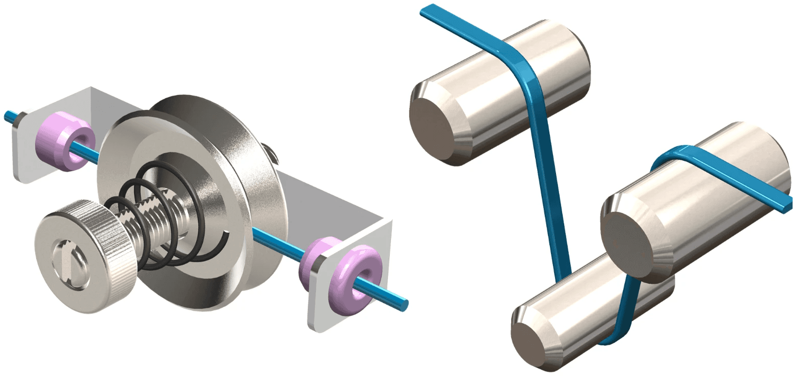
.Early concepts focused on actively maintaining constant fiber tension before deposition. Drawing inspiration from tensioning mechanisms used in textile and knitting machinery, several concepts were evaluated before developing a spring-loaded tensioner. An adjustable compression spring applied a controlled normal force to the fiber path, allowing tension to be tuned while accommodating changes in feed speed during winding.
Troubleshooting | Bending
Testing revealed that the wound fiber already maintained the tension required for deposition; the larger problem was excessive and inconsistent resistance upstream. Sharp changes in feed direction over-tensioned and frayed the tow, particularly as it was redirected toward the moving toolhead.
The system was redesigned around passive guidance rather than active tensioning. A 3D-printed pivoting guide continuously aligned itself with the toolhead, while a ceramic eyelet provided a low-friction, wear-resistant contact surface that prevented both fiber damage and abrasion of the printed component. Feeding the tow through a flexible tube created a smoother path to the toolhead, eliminating the high-friction 90° redirection and substantially reducing unwanted tension.

Engineering GridWinder | Toolhead

Toolhead Design
The toolhead was designed to guide tensioned fiber around closely spaced pins while minimizing the moving mass of the gantry. Early iterations used a multi-piece guide assembly weighing 137 g, which increased inertia and limited achievable acceleration.
The final design reduced the assembly to 43 g by integrating the fiber guide into a lightweight machined structure. Tube diameter was evaluated against fiber tension and material yield strength to ensure the slender guide could withstand bending during winding. A ceramic eyelet provides a low-friction interface at the inlet, while the curved outlet deposits fiber closely around each pin without damaging or excessively bending the tow.


Polygonal Fabrics

Localized Stiffnesses
GridWinder Today
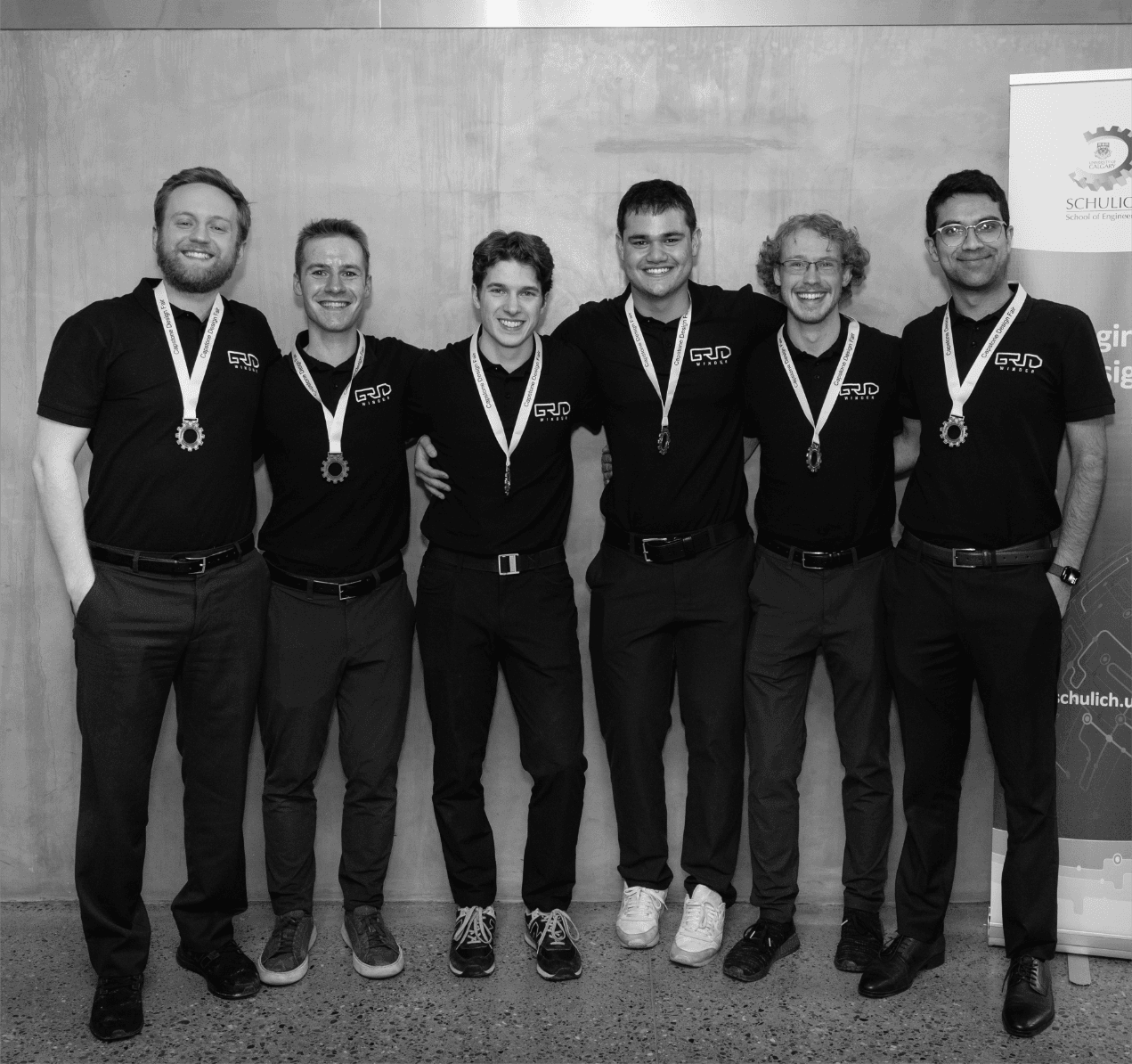
GridWinder won the Gold Medal at the University of Calgary Engineering Design Competition and received the MISUMI University Program Grant, a competitive application-based award supporting innovative student engineering projects. Most recently, the project was recognized as a standout innovation in the President’s Address at the University of Calgary’s 2026 convocation.
Today, GridWinder is competing in the 2026 James Dyson Award and continues to be researched through the Laboratory of Engineering Materials, with work toward a future publication exploring its potential to reduce material waste, improve manufacturing efficiency, and enable the more sustainable adoption of composite materials.

Empowering Makers
Composite manufacturing made affordable.
Redefine Fabrication
Replacing fabrics with additive fiber winding.
Eliminating Waste
Zero scrapped off-cuts in making parts.