Student Organization For Aerospace Research

Explore some of my highlighted projects from student rocketry.

Rothney Astrophysical Observatory

Foothills County, Alberta

1st Place 10,000ft SRAD Rocket

2024 Spaceport America Cup

Student Designed Sounding Rockets

Taking ambitious aerospace projects from first principles to flight.

Rothney Astrophysical Observatory

Background

SOAR's Story

Founded in 2015 alongside the Aero-Core Lab at the University of Calgary and having launched 6 major rockets since, SOAR is a student team that focuses on designing, developing, and manufacturing experimental sounding rockets.

Our Vision

SOAR exists to give students the opportunity to take engineering beyond the classroom. Through the design, manufacturing, testing, and launch of increasingly ambitious rockets, the team provides an environment where students can turn theory into flight-ready hardware while pushing the capabilities of student rocketry.

Background

SOAR's Story

Founded in 2015 alongside the Aero-Core Lab at the University of Calgary and having launched 6 major rockets since, SOAR is a student team that focuses on designing, developing, and manufacturing experimental sounding rockets.

Our Vision

SOAR exists to give students the opportunity to take engineering beyond the classroom. Through the design, manufacturing, testing, and launch of increasingly ambitious rockets, the team provides an environment where students can turn theory into flight-ready hardware while pushing the capabilities of student rocketry.

Since joining the team after my second year, I have contributed to projects spanning ground communications, composite structures, actuators, pressure vessels, and nozzles.


As my role grew, I developed a passion for design for manufacturing and preparing the CAM needed to bring my designs to life.

Endcaps & Actuator

Featured Club Projects

Below are two featured projects: redesigned pressure-vessel endcaps developed for our latest launch and upcoming 100,000-ft Athena launch, and a lightweight rack-and-pinion valve actuator engineered for reliable flight operation used in our 2024 Ouroboros launch.

Skip to Actuator

Skip to Actuator

Featured Club Projects

Below are two featured projects: redesigned pressure-vessel endcaps developed for our latest launch and upcoming 100,000-ft Athena launch, and a lightweight rack-and-pinion valve actuator engineered for reliable flight operation used in our 2024 Ouroboros launch.

Skip to Actuator

Pressure Vessel Endcaps

Mar 7, 2026

Aegis PV Upper Cap

Mar 7, 2026

Aegis PV Upper Cap

Mar 2, 2026

Aegis PV Lower Cap
  1. Project Design Objective

The project focused on redesigning the sealing end caps for Aegis' oxidizer pressure vessel. The previous flat design was structurally inefficient under pressure and carried unnecessary mass. The new end caps were developed to reduce weight while integrating sealing, fluid connections, retention, avionics mounting, and serviceability into a manufacturable component.

Key Requirements:

  • 1000 psi maximum operating pressure

  • FOS ≥ 2 against ultimate failure

  • −80°C to 40°C operating range

  • Manufactured from nitrous compatible materials

  • Size 258 O-ring interface

  • Integrated ORB ports for sealing

Designing Around Pressure

With an outside diameter to thickness ratio over 20, the end cap geometry satisfied the thin-wall assumption used for sizing. With the previous pressure vessel being cylindrical, hoop stress is twice the longitudinal stress, making it the governing membrane stress.

However, by changing the geometry of the endcaps from being flat to spherical results in only half the maximum membrane stress of an equivalent cylindrical vessel under the same pressure, radius, and thickness. Hemispheres offer the greatest structural efficiency, but require substantially more axial space. This motivated the choice to investigate a semi-elliptical profile balancing pressure efficiency, packaging, mass, and manufacturability.

It was from these preliminary results that it became evident an optimal height to thickness ratio existed for the most mass efficient design. Simply decreasing the endcap height did not produce a proportional reduction in mass, as geometries with less uniform load sharing required thicker walls. This model was further refined with smaller increments in the FEA to determine endcap heights of 2.525" and 1.903" for the upper and lower endcaps respectively.

  1. Material Selection

The previous endcaps used 6061-T6 aluminum. For Aegis, the design transitioned to 7075-T6, where the substantially greater strength allowed thinner structural sections, while remaining compatible with the nitrous oxidizer system. Although 7075 is slightly denser than 6061, its significantly higher strength provides better structural performance per unit mass for this application.


  1. Designing The Seal

The end cap geometry was built around the pressure seal rather than treating it as a secondary feature. A size 258 O-ring was selected, with the resulting gland requirements establishing a final end-cap OD of 6.247 in.

Two VMQ 258 O-rings lubricated with Krytox GPL 203 provide the sealing interface, with gland geometry based on Parker O-Ring Handbook recommendations. This created a controlled precision interface around which the remaining structure could be optimized.

FOS & FEA Setup

After having run preliminary FEA studies on both the lower and upper endcaps, the resulting factor of safety were 2.23 and 2.75 respectively with both seeing a max deflection of 5 thou.

The constraints used in this study include a fixed support on the face in contact with the 'radax' retention ring (flat above O-ring groove) with an 1000 psi pressure force applied on the PV side.

GridWinder feature
  1. FEA Results Across 120°C

1.
40°C Results | Deformation

Maximum deformation of 6.9thou.

2.
40°C Results | FOS

Minimum FOS of 2.8.

3.
-80°C Results | Deformation

Maximum deformation of 11.6thou.

4.
-80°C Results | FOS

Minimum FOS of 0.83. ('Radax' mating face on top of O-ring grooves.)

GridWinder feature

ORB-12 & ORB-04 instrumentation ports are used in the lower end cap as integrated fluid interfaces.

Machined flats on the bottom end cap are used for wrench access to reduce tabletop assembly time.

The upper cap is designed with four threaded mounting pillars for avionics integration rods.

¼-20 threaded extraction holes on the outer rim to can extract the cap from the vessel without damaging components.

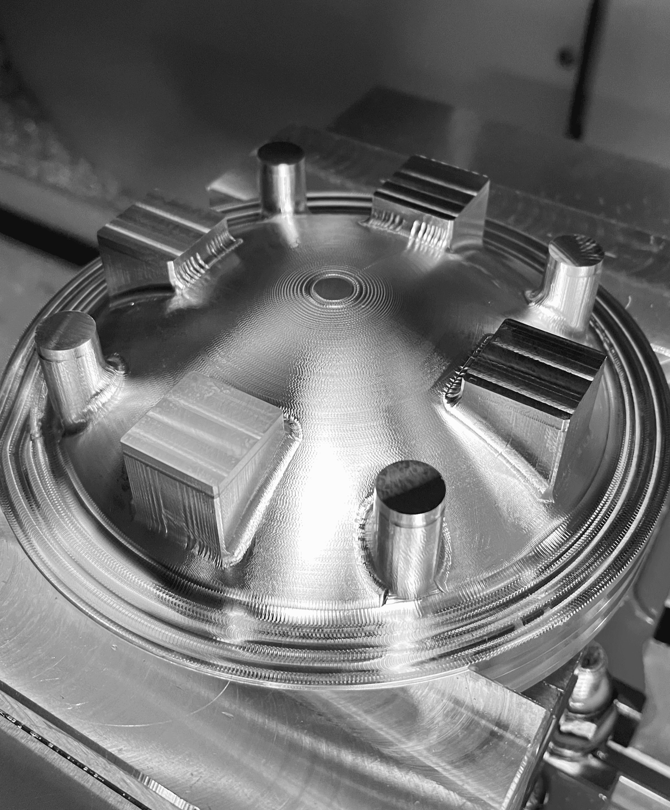
  1. CNC Machining

The previous endcaps used 6061-T6 aluminum. For Aegis, the design transitioned to 7075-T6, where the substantially greater strength allowed thinner structural sections, while remaining compatible with the nitrous oxidizer system. Although 7075 is slightly denser than 6061, its significantly higher strength provides better structural performance per unit mass for this application.


Optimizing Setups

The end cap geometry was built around the pressure seal rather than treating it as a secondary feature. A size 258 O-ring was selected, with the resulting gland requirements establishing a final end-cap OD of 6.247 in.

Two VMQ 258 O-rings lubricated with Krytox GPL 203 provide the sealing interface, with gland geometry based on Parker O-Ring Handbook recommendations. This created a controlled precision interface around which the remaining structure could be optimized.

Compact Rack & Pinion Actuator

  1. Project Objective

Remotely controlling oxidizer flow is essential in hybrid rocket systems, but conventional rack-and-pinion pneumatic actuators can weigh around 4 lb, making existing industrial solutions poorly suited to flight hardware. The goal was to redesign this technology around the requirements of our newest rocket at the time, Ouroboros, producing a compact actuator capable of rotating a standard 26 in-lb ball valve through 90° while weighing as little as possible.

  • 800 psi actuation pressure

  • −50°C to 30°C operating range

  • FOS ≥ 2 for non-COTS components

  • 26in-lb valve torque

  • Nitrous-oxide compatible

  • Minimize both mass and width

Mar 10, 2024

Ouroboros Valve Actuator

Final design: 0.48 lb · 1.6 in wide · FOS 2 · 1,071-cycle limiting rating.

  1. How The Actuator Works

Pressurized nitrous enters the chamber and drives the piston forward. The rack converts this linear displacement into pinion rotation, turning the connected ball valve 90°. Once pressure is released, the compressed springs drive the piston backward and return the valve to its original position.

  1. Sizing From First Principles

The actuator was sized around pneumatic force, valve torque, and seal friction. Piston diameter determined the force available at 800 psi, while O-ring friction reduced the usable output. These forces were then used to size the piston and pinion needed to reliably rotate the valve.

  1. Optimizing With MATLAB

Before any detailed CAD began, a custom MATLAB program was developed. This program iterated through standard Parker O-ring sizes, using each piston diameter to calculate the required pinion geometry and predict the resulting actuator size and mass. The lowest-scoring configuration was then carried forward into detailed design.

  1. Seal friction is calculated

  2. Pneumatic force determined

  3. Pinion is sized for valve torque & gear strength

  4. Pressure vessel wall thickness estimated

  5. Required piston travel is calculated

  6. Actuator weight and width predicted

  7. The design is scored using 75% weight & 25% width

  8. The lowest-scoring configuration is selected

Before any detailed CAD began, a custom MATLAB program was developed. This program iterated through standard Parker O-ring sizes, using each piston diameter to calculate the required pinion geometry and predict the resulting actuator size and mass. The lowest-scoring configuration was then carried forward into detailed design.

  1. Seal friction is calculated

  2. Pneumatic force determined

  3. Pinion is sized for valve torque & gear strength

  4. Pressure vessel wall thickness estimated

  5. Required piston travel is calculated

  6. Actuator weight and width predicted

  7. The design is scored using 75% weight & 25% width

  8. The lowest-scoring configuration is selected

  1. Mapping Operating Loads

A secondary MATLAB program determined the loads experienced by each major component during operation:

  • 478 lb maximum piston/bolt pressure load

  • 389 lb maximum compressed spring force

  • 389 lb maximum gear-opening load

  • 300 lb gear-closing load

  • 158 lb body impact/return load

  • 89 lb end-cap face load

A secondary MATLAB program determined the loads experienced by each major component during operation:

  • 478 lb maximum piston/bolt pressure load

  • 389 lb maximum compressed spring force

  • 389 lb maximum gear-opening load

  • 300 lb gear-closing load

  • 158 lb body impact/return load

  • 89 lb end-cap face load

  1. Sizing From First Principles

The springs were evaluated using alternating and mean torsional stress with a Goodman fatigue relationship, followed by an S-N-based cycle estimate. The design targeted 99% reliability because even relatively small mechanical failures can become critical in a rocket system.

Likewise, the six end-cap bolts were evaluated under a load cycle ranging from 158 to 478 lb total, producing a calculated bolt fatigue life of 7,322 cycles at 99% reliability.

  1. Designing Springs For Fatigue

Two concentric compression springs were used to generate the required return force without significantly increasing actuator length. The springs were sized in MATLAB for load sharing, spring rate, stress, packaging, and fatigue life, ensuring the valve could reliably return after pressure was released.

  • Dual concentric springs minimize overall length

  • Spring rate calculated from wire and coil geometry

  • Load shared between inner and outer springs

  • Evaluated for mean and alternating stress

  • Goodman fatigue analysis used for cyclic loading

  • Designed around 99% reliability

  • Limiting calculated life: 1,071 cycles

  • High-carbon steel selected for fatigue strength

Two concentric compression springs were used to generate the required return force without significantly increasing actuator length. The springs were sized in MATLAB for load sharing, spring rate, stress, packaging, and fatigue life, ensuring the valve could reliably return after pressure was released.

  • Dual concentric springs minimize overall length

  • Spring rate calculated from wire and coil geometry

  • Load shared between inner and outer springs

  • Evaluated for mean and alternating stress

  • Goodman fatigue analysis used for cyclic loading

  • Designed around 99% reliability

  • Limiting calculated life: 1,071 cycles

  • High-carbon steel selected for fatigue strength

The actuator was designed for simple assembly, alignment, and maintenance. A single-piston architecture prevents binding, while the elongated end cap both mounts the return springs and limits travel to exactly 90°. A slide-on housing simplifies pinion installation, with integrated gear backlash, piston extraction threads, an alignment flat, ORB inlet, and breathing hole improving reliability and serviceability.

The actuator was designed for simple assembly, alignment, and maintenance. A single-piston architecture prevents binding, while the elongated end cap both mounts the return springs and limits travel to exactly 90°. A slide-on housing simplifies pinion installation, with integrated gear backlash, piston extraction threads, an alignment flat, ORB inlet, and breathing hole improving reliability and serviceability.

Assembly & Service

The actuator was designed for simple assembly, alignment, and maintenance. A single-piston architecture prevents binding, while the elongated end cap both mounts the return springs and limits travel to exactly 90°. A slide-on housing simplifies pinion installation, with integrated gear backlash, piston extraction threads, an alignment flat, ORB inlet, and breathing hole improving reliability and serviceability.

Assembly & Service

5._FEA & Failure Analysis

Body burst FEA results, FOS 6.28

Endcap piston contact FEA, FOS 4.27

Rack tooth FEA results, 3.61

Pinion gear FEA results, FOS 2.00

Analytical and MATLAB models established the initial dimensions before SolidWorks FEA was used to capture complex geometry and load paths. Components were iteratively refined to maintain a minimum FOS of 2, with the pinion gear becoming the governing component at exactly 2.0, minimizing unnecessary material while meeting structural requirements.

6._The Sealing System

The actuator’s seals had to maintain pressure while surviving repeated piston motion and temperatures as low as −50°C. The Parker O-Ring Handbook guided the reciprocating seal geometry, while material selection considered nitrous compatibility, compression set, thermal behavior, and tear resistance, ultimately leading to EPDM.

Lubricants were separately evaluated for EPDM compatibility and actuator requirements. The study identified Super Lube Silicone Lubricant, Brit-Lube Crystal Lube, and LOX-8 as suitable options. Super Lube offered the lowest cost, while LOX-8 stood out for its NASA testing and paste consistency, with both also being readily available COTS solutions.

More Than a Rocket

Multidisciplinary Projects

SOAR taught me how every engineering discipline comes together to achieve what none could accomplish alone.

Design Knowledge

Every challenge begins by defining the problem, uncovering unknowns, and experimenting toward a solution.

Refining Teamwork

SOAR taught me how to empower a team to achieve goals that once seemed out of reach.